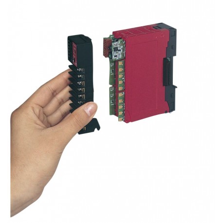
PUMB 2 Channel Controller
New
Multi-loop module controller, provides expandable capability at reduced cost per loop.
Multi-loop module controller
Provides expandable capability at reduced cost per loop.
Main features and benefits
- Full integration of PLC functions, with digital input/output signal processing up to 16-k step and 300 points -for Programmable Logic Controllers performances.
- PC configuration - makes installation easier
- Detachable terminals - reduce wiring and machine downtime
- Multi loop control - reduces system costs
- Multi zone control - provide closer control of interacting control loops
- Modular design - reduces initial cost without restricting future development
- Fast CPU speed - provides a universal controller
- Application Assistance - The support you need to get your production up and running
Fuji PUM series is a "back of panel" controller. This make it an ideal process controller to work with HMI touch screens, such has Hakko Monitouch series.
The units are designed to operate on their own, or in conjunction with a large range of PLC's (programmable logic controllers), HMI's and SCADA systems.
Configuration is carried out via a PC link. Specific applications can be pre programmed by our engineers prior to despatch.
When they are used on their own, the PUM range of modules can handle single or multi loop control applications and provide PLC, alarm or communication functions.
Alternatively when they are used with a PLC, time consuming operations such as fast response multi loop control can be delegated to the PUM, allowing your PLC to focus on supervisory or safety critical operations.
The modular design of the Fuji PUM allows individual units to communicate to each other without wiring. For example additional alarms automatically become available on the additions of a digital output module with no inter-module wiring.
Standardisation of detachable terminals also reduce wiring and re-wiring while you swap modules.
Full integration of PLC functions, with digital input/output signal processing up to 16-k step and 300 points - for programmable Logic Controller performances.
- Thermocouple: (±0.1%FS±1digit±1°C) or ± 1.5°C,
whichever is larger - Thermocouple B: 0 to 400°C range;
±5%FS± 1digit±1°C - Thermocouple R: 0 to 500°C range;
±1%FS± 1digit±1°C - • Resistance bulb input:
(±0.1%FS±1digit) or ±0.25°C, whichever is larger - Voltage input, current input:
±0.1%FS± 1digit - Thermocouple, voltage input (mV): 1 MΩ or more
- Voltage input (V): 1MΩ
- Current input: 250Ω
- Thermocouple, voltage input (mV):0.1%FS per 100Ω
- Voltage input (V): 0.1%FS per 500Ω
- Resistance bulb input: 10Ω or less (per cable)
- Voltage (V) input: +35 V / -10 V DC
- Current input: ±25 mA DC
- Thermocouple/Resistance bulb/Voltage (mV) input: ±5 V DC
- Normal mode: 40 dB (50/60 Hz) or more
- Common mode: 120 dB (50/60 Hz) or more
- User adjustment:
± 50%FS both for zero point and span point - Square-root extractor: OFF or cut point from 0.0 to 125.0%
- Input filter: 0.0 to 900.0 sec. for time constant.
- Contact structure: SPDT contact (Do4 used)
- Contact capacity: 220V AC / 30 V DC, 3A (Resistive load) 220V AC / 30 V DC, 1A (Inductive load)
- Life: 100,000 operations (rated load)
2. SSR/SSC driver output (Voltage pulse) - Load resistance: 600Ω or more
- Accuracy: ±0.2%FS
- Linearity: ±0.2%FS
- Load resistance: 600Ω or less
General specifications
(1) Power supply voltage: 100V (-15%) to 240V (+10%) AC, 50/60 Hz
(2) Power consumption: 15 VA or less (100 V AC) 20 VA or less (220 V AC)
(3) Insulation resistance: 20 MΩ or more (500 V DC)
(4) Withstand voltage: Power supply ↔ All terminals; 1500 V AC for 1 minute Relay output ↔ All terminals; 1500 V AC for 1 minute Others; 500 V AC for 1 minute
(5) Applicable standard (plan): UL, C-UL, CE Mark
Input section
2-1 Measurement value input
(1) Number of inputs: 1 or 2 (Option)
(2) Input signal type:
Thermocouple :J, K, R, B, S, T, E, PR40/20, N, PL-II,
WRe5-26
Resistance bulb :Pt100Ω (3-wire)
Voltage :0 to 10 mV DC, 0 to 50 mV DC,
1 to 5 V DC, 0 to 5 V DC, 0 to 10 V DC
Current :4 to 20 mA DC, 0 to 20 mA DC
(3) Measurement range:
Refer to the measurement range table.
(4) Input indication accuracy (Ambient temperature: 23°C):
(5) Input sampling cycle: 50 ms
(6) Input impedance
(7) Influence of source resistance / Permissible wiring
resistance
(8) Permissible input voltage
(9) Noise reduction ratio
(10) Input value correction function (Input conditioner)
Output section
3-1 Control output
(1) Number of points: 1
(2) Type: Select one as follows.
1. Relay contact output
Rating: 12 V DC (10 to 15 V DC) / Maximum current: 20mA (provided with
protection against short circuit)
3. Current output (4 to 20 mA DC)


